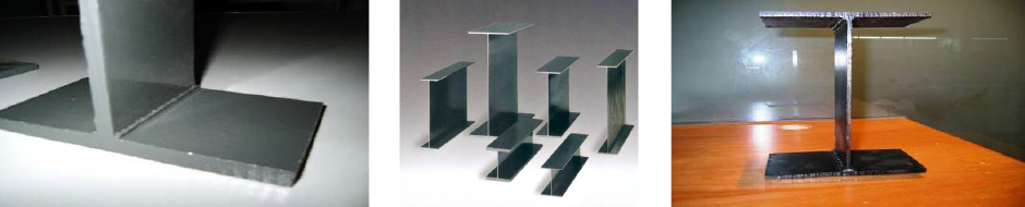
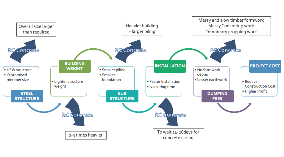
HFW members could achieve sizes that are not found in Hot-rolled steel.
This in turn will provide an exact member size requires by design hence lowering the cost of material
To design requirement thickness & width before feeding into the production line

From the uncoiled steel rolls before entering the Patented” weld head for High Frequency Welding.
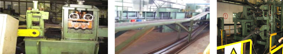
Being Welded bythe High Frequency Welding Process (automated process)
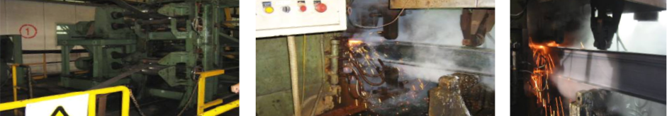
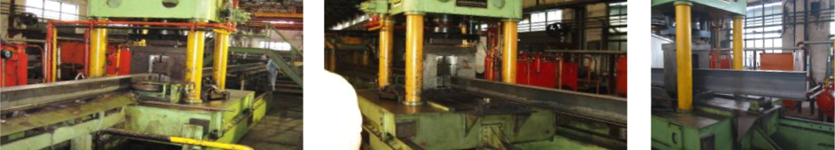
After stress relieve & straightening (automated process)
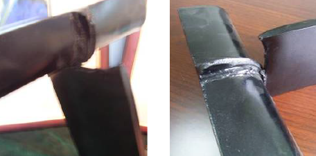

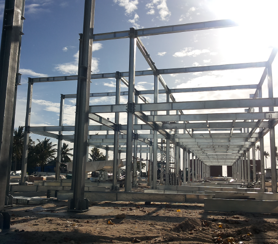
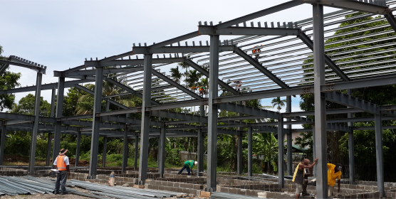
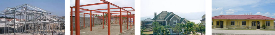
Widely use for secondary structure for large building.

widely use as Main structurer for Muti storey residential house.
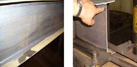
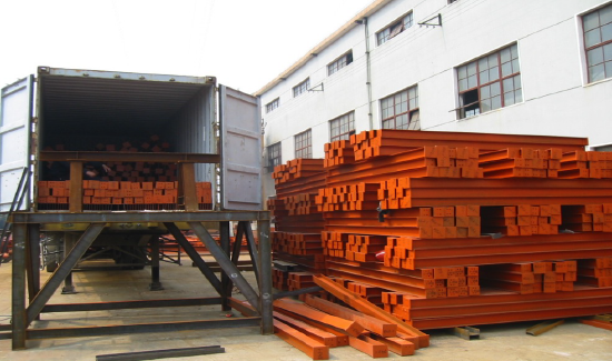
Applicable for thicknesses from 2.5mm, resulting in Light weight steel structure No Heavy hoisting euipments are required for Installation
Main Structure for Residential Buildings ( 3 storey & Below) Secondary Structure for High Rise Buildings
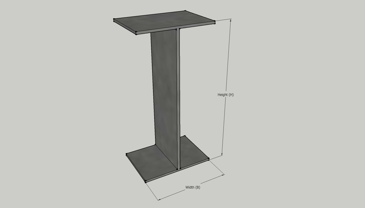
Production Range Of HFW H Section
|
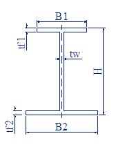
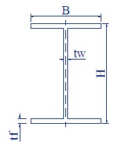
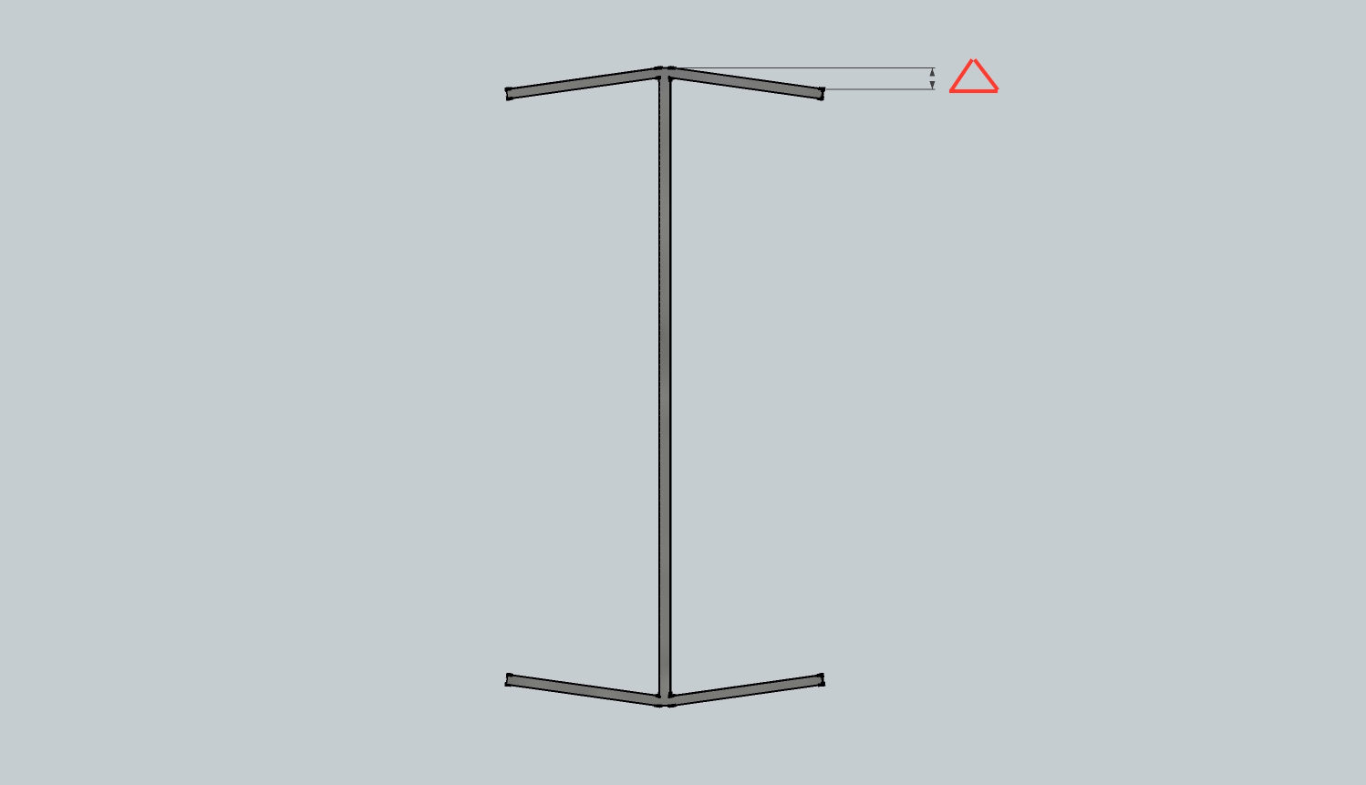
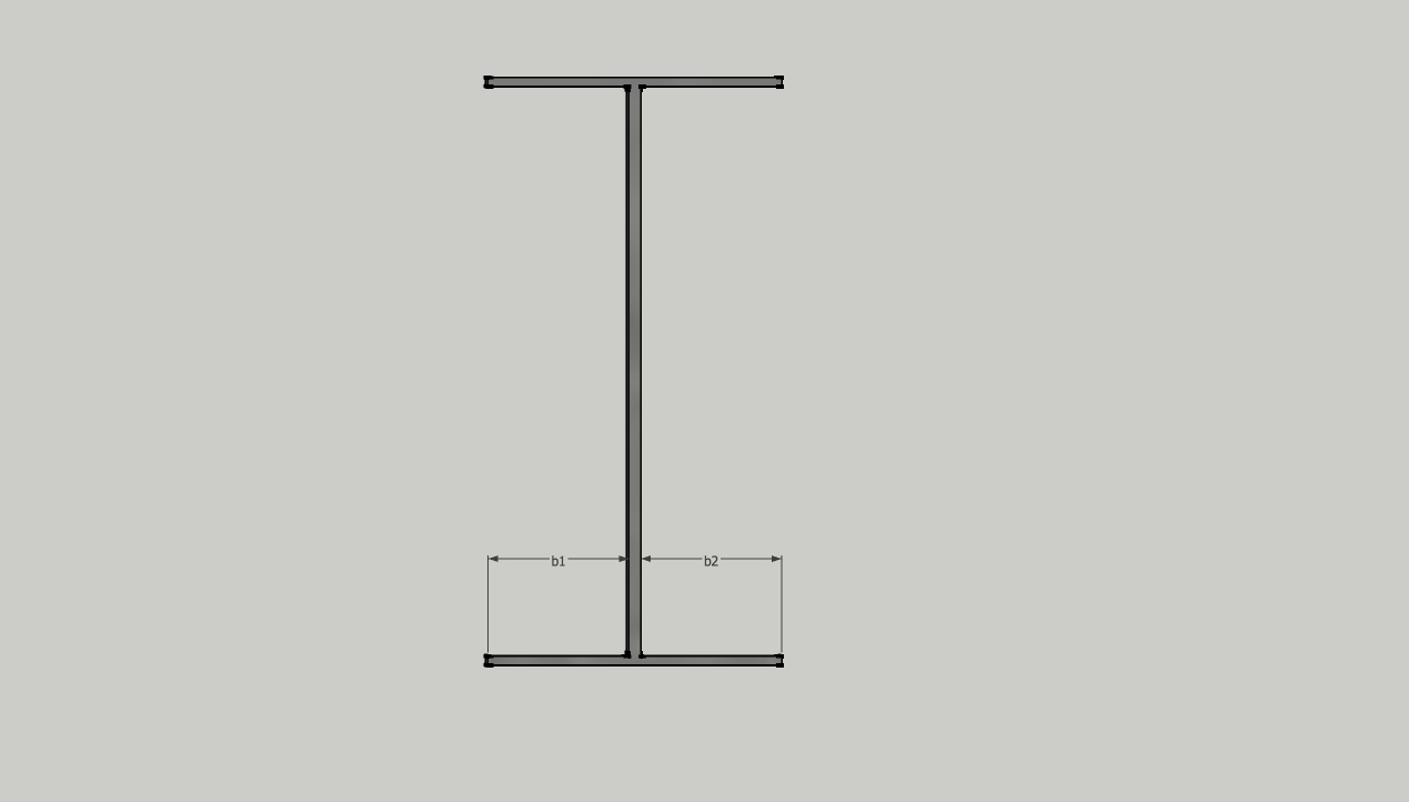
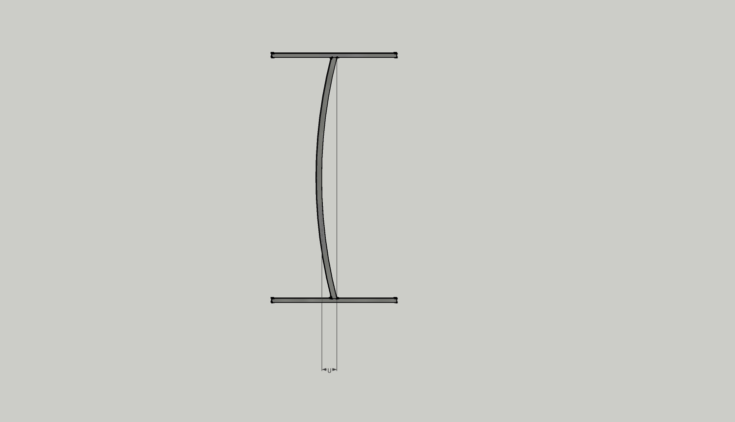
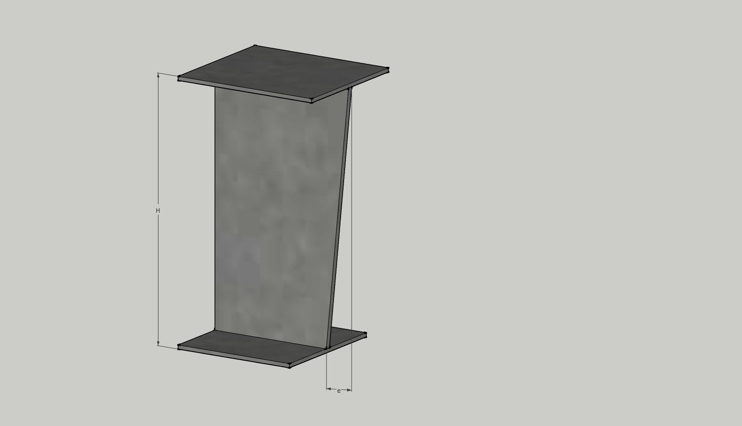
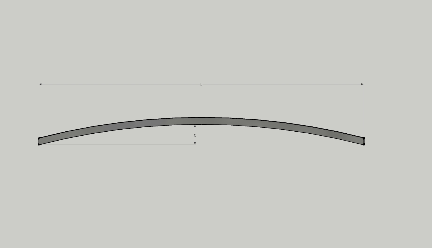
Dimension, Shapes & Tolerances
Mechanical Properties GB/T 1591-94
|
||||||||||||||||||||||||||||||||||||||||||||||||||||||||||||||||||||||||||||||||||||||
| Serial No. |
Thickness (mm) |
TensileStrength ( N/mm2) |
Min. Yield Strength (N/mm2) |
Elongation | Bending Test 180 | V-Impact Testing | |
| d=Bending Dia. | Testing Temperature | Joule (J) | |||||
| a=Testing Thickness | |||||||
| Q345 (16Mn) | ≤16 | 510-660 | ≥345 | ≥22 | d=2a | - | - |
| >16~25 | 490-640 | ≥325 | ≥21 | d=3a | 20 | ≥27 | |
| >25~36 | 470-620 | ≥315 | d=3a | 0 | ≥27 | ||
| SM490YA | ≤16 | 490-610 | 365 | ≥19 | - | - | - |
| SM490YB | >16~40 | 355 | - | 0 | ≥27 | ||
| S.no | Dimensions in mm |
Cross Sectional Area (A ) in mm2 |
Weight kg/m | |||
| Height (H) |
Width (B) |
Thickness of Web (tw) |
Thickness of Flange (tf ) |
|||
| 1 | 100 | 50 | 2.3 | 3.2 | 5.35 | 4.2 |
| 2 | 3.2 | 4.5 | 7.41 | 5.82 | ||
| 3 | 100 | 4.5 | 6.0 | 15.96 | 12.53 | |
| 4 | 6.0 | 8.0 | 21.04 | 16.52 | ||
| 5 | 120 | 120 | 3.2 | 4.5 | 14.35 | 11.27 |
| 6 | 4.5 | 6.0 | 19.26 | 15.12 | ||
| 7 | 150 | 75 | 3.2 | 4.5 | 11.26 | 8.84 |
| 8 | 4.5 | 6.0 | 15.21 | 11.94 | ||
| 9 | 100 | 3.2 | 4.5 | 13.51 | 10.61 | |
| 10 | 4.5 | 6.0 | 18.21 | 14.29 | ||
| 11 | 150 | 4.5 | 6.0 | 24.21 | 19 | |
| 12 | 6.0 | 8.0 | 32.04 | 25.15 | ||
| 13 | 200 | 100 | 3.0 | 3.0 | 11.82 | 9.28 |
| 14 | 3.2 | 4.5 | 15.11 | 11.86 | ||
| 15 | 4.5 | 6.0 | 20.46 | 16.06 | ||
| 16 | 6.0 | 8.0 | 27.04 | 21.23 | ||
| 17 | 150 | 3.2 | 4.5 | 19.61 | 15.4 | |
| 18 | 4.5 | 6.0 | 26.46 | 20.77 | ||
| 19 | 6.0 | 8.0 | 35.04 | 27.51 | ||
| 20 | 200 | 6.0 | 8.0 | 43.04 | 33.79 | |
| 21 | 250 | 125 | 3.0 | 3.0 | 14.82 | 11.63 |
| 22 | 3.2 | 4.5 | 18.96 | 14.89 | ||
| 23 | 125 | 4.5 | 6.0 | 25.71 | 20.18 | |
| 24 | 4.5 | 8.0 | 30.53 | 23.97 | ||
| 25 | 6.0 | 8.0 | 34.04 | 26.72 | ||
| 26 | 150 | 3.2 | 4.5 | 21.21 | 16.65 | |
| 27 | 4.5 | 6.0 | 28.71 | 22.54 | ||
| 28 | 4.5 | 8.0 | 34.53 | 27.11 | ||
| 29 | 6.0 | 8.0 | 38.04 | 29.86 | ||
| 30 | 200 | 6.0 | 8.0 | 46.04 | 36.14 | |
| 31 | 300 | 150 | 3.2 | 4.5 | 22.81 | 17.91 |
| 32 | 4.5 | 6.0 | 30.96 | 24.3 | ||
| 33 | 4.5 | 8.0 | 36.78 | 28.87 | ||
| 34 | 6.0 | 8.0 | 41.04 | 32.22 | ||
| 35 | 200 | 6.0 | 8.0 | 49.04 | 38.5 | |
| 36 | 350 | 150 | 3.2 | 4.5 | 24.41 | 19.16 |
| 37 | 4.5 | 6.0 | 33.21 | 26.07 | ||
| 38 | 6.0 | 8.0 | 44.04 | 34.57 | ||
| 39 | 175 | 4.5 | 6.0 | 36.21 | 28.42 | |
| 40 | 4.5 | 8.0 | 43.03 | 33.78 | ||
| 41 | 6.0 | 8.0 | 48.04 | 37.71 | ||
| 42 | 200 | 6.0 | 8.0 | 52.04 | 40.85 | |
| 43 | 400 | 150 | 4.5 | 8.0 | 41.28 | 32.4 |
| 44 | 200 | 6.0 | 8.0 | 55.04 | 43.21 | |
| 45 | 4.5 | 9.0 | 53.19 | 41.75 | ||
| 46 | 6.0 | 9.0 | 58.92 | 46.25 | ||
| 47 | 450 | 200 | 4.5 | 8.0 | 51.53 | 40.45 |
| 48 | 6.0 | 8.0 | 58.04 | 45.56 | ||
| 49 | 4.5 | 9.0 | 55.44 | 43.52 | ||
| 50 | 6.0 | 9.0 | 61.92 | 48.61 | ||
| 51 | 250 | 4.5 | 8.0 | 59.53 | 46.73 | |
| 52 | 6.0 | 8.0 | 66.04 | 51.84 | ||
| 53 | 4.5 | 9.0 | 64.44 | 50.59 | ||
| 54 | 6.0 | 9.0 | 70.92 | 55.67 | ||
| 55 | 500 | 500 | 4.5 | 8.0 | 53.78 | 42.22 |
| 56 | 6.0 | 8.0 | 61.04 | 47.92 | ||
| 57 | 4.5 | 9.0 | 57.69 | 45.29 | ||
| 58 | 6.0 | 9.0 | 64.92 | 50.96 | ||
| 59 | 250 | 4.5 | 8.0 | 61.78 | 48.5 | |
| 60 | 6.0 | 8.0 | 69.04 | 54.2 | ||
| 61 | 4.5 | 9.0 | 66.69 | 52.35 | ||
| 62 | 6.0 | 9.0 | 73.92 | 58.03 | ||
| 63 | 600 | 200 | 6.0 | 10.0 | 74.8 | 58.72 |
| 64 | 300 | 6.0 | 10.0 | 94.8 | 74.42 | |